
Motor and hand control.
There will be additional screws if you have a headboard or a drawer base
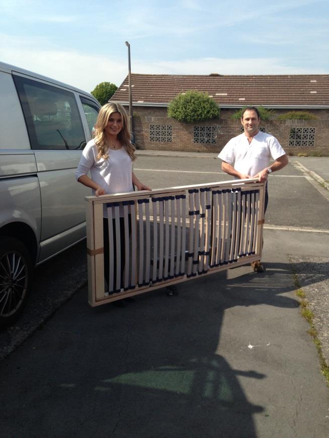
The Adjustable Bed Mechanism (Shown in Assembly)
Head end, Foot end & 2 Sides (Shown in assembly)
Mattress

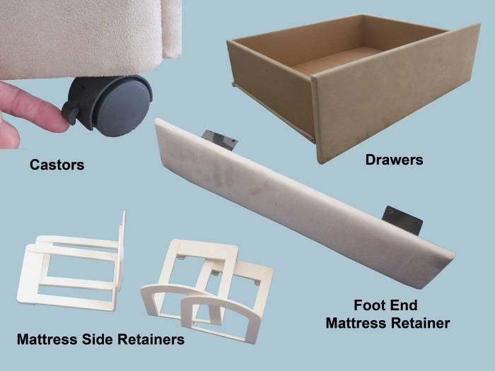
Castors instead of wooden feet
4 Nylon mattress retaining bars (Pre-drilled)
Complete with 8 x 12mm screws
Upholstered foot end mattress retaining panel.
Drawers – (See website acessorie page)
Mattress Upgrade – (See mattress options)
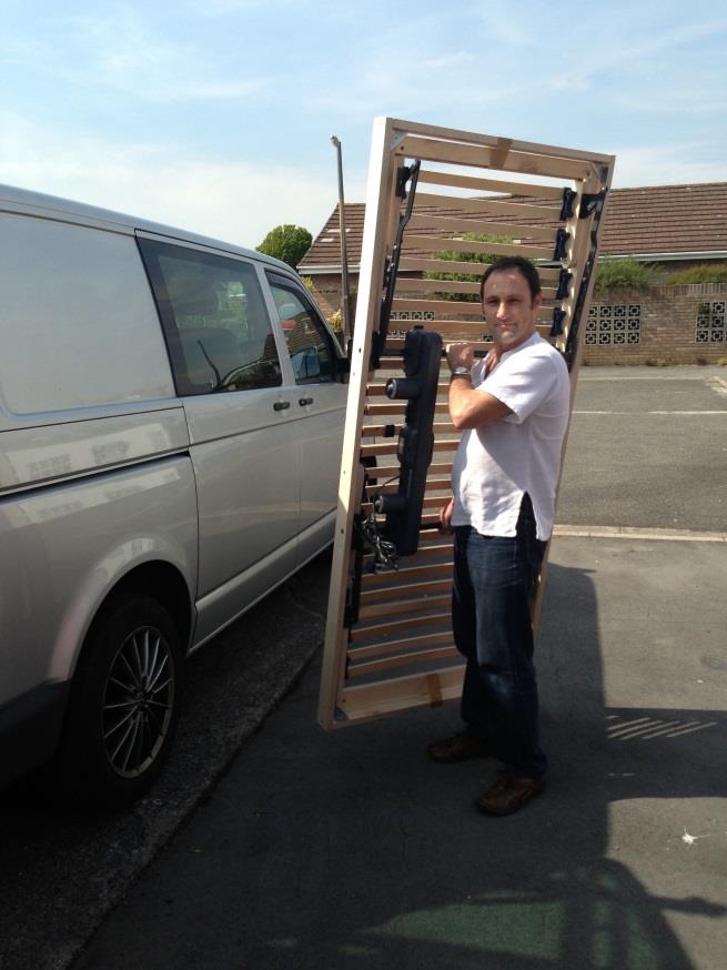
The most awkward component to lift is the mechanism. One person can maneuver this quite easily by taking the weight on one of the drive bars that run across the frame, lift using your legs not your back.Although not particularly heavy it is always easier for two people and you are less likely to smash the house up in the process.
Note. The motors will not be pre-fitted. Please follow the separate installation guide.

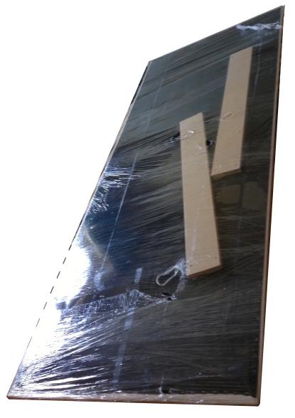
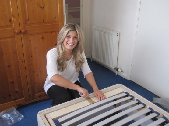
Stand the head end against a wall. The brackets are already fixed in the correct position. Lay the sides and foot end panels on the floor.
Note. Headboards over 4’width. The headboard is separate

Twin beds will be packed with both head and foot panels. The square cut panels are the head end and the rounded panels are the foot end which match the sides.

Two strong nylon clips are supplied with twin beds. Once the two bases are assembled clip them together from underneath. One clip near the head and foot ends.
Wider headboards are packed with struts already attached with one screw.
Swivel the struts straight and screw the 30mm screws into the pre-drilled holes.
Position the headboard on the back panels and fasten the remaining screws.
Note: Headboards up to 3’ are Pre assembled
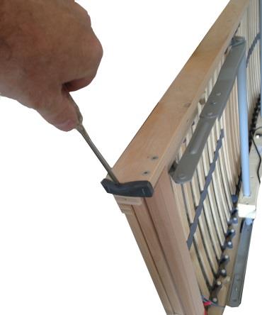
The mechanism has protective corners for transport. These can be removed to allow the mechanism to fit if it is too tight. Remove any sharp staples with pliers.
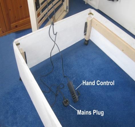
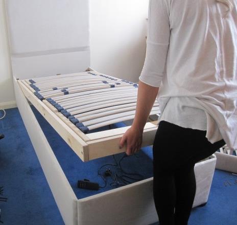
With the mechanism leaned against a wall or balanced close to the bed, Fit the motors (see separate guide) drop the hand control and power cable inside the bed base.
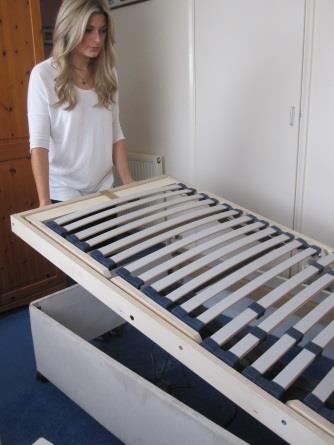
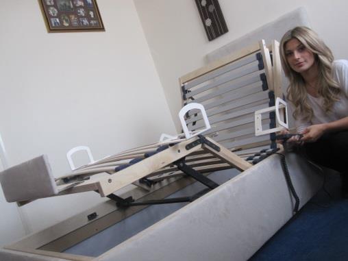
Carefully lower the head end onto the battens on the inside edge of the two sides and slide the mechanism towards the head end and onto the corner blocks.
Lower the foot end into the base and being careful not to trap your fingers then pull the mechanism back to be hard up against the foot end of the base.
As you can see the foot end of the mechanism is tight against the foot end of the base, however you should expect to see a gap at the head end. Cut the packing at the head and foot.

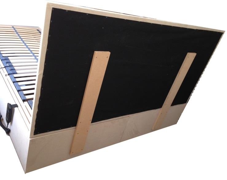
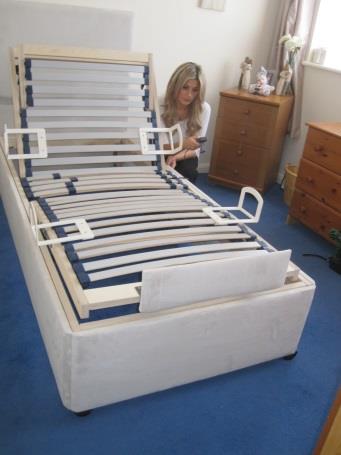
Using a tape measure, centralize the optional upholstered foot end retainer and screw it down using the remaining four 20mm screws.
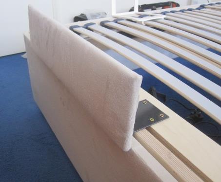
The mattress retaining panel should be lined up so that the inside face of the panel is flush to the front face of the foot panel which will in turn mean that the mattress aligns nicely with the foot end of the base.
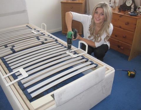
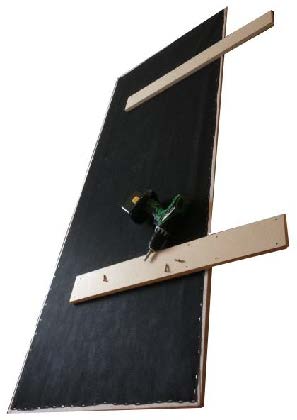
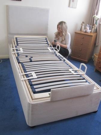
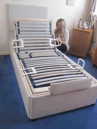
Locate the four pre-drilled mattress retaining bars and screw them down using the eight 12mm screws. The bars should be positioned on the pair of slats in the shoulder and thigh area opposite each other.

The outside of the mattress retaining bars should be flush with the outside face of the upholstered side panels. This will keep the mattress from moving sideways.

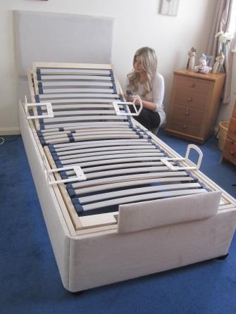
You can now manually lift the back section of the mechanism, reach inside and feed the plug under the back of the base and plug it in.
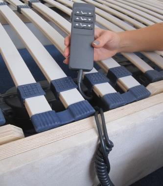
Locate the hand control and feed that up between the central slats with the tensioners. This is not difficult as the slats are flexible. This will give more cable and can be fed through on the left or right side.
You are now ready to familiarise yourself with the function of the electric adjustable bed.
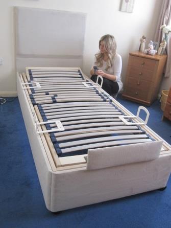
The motion will be nice, smooth and quiet.
The back will stop at its maximum point controlled by limit switches inside the motor.

A nice feature of the head end, it will progressively raise the neck section to the perfect angle.
Once the neck section has reached a certain point the back will begin to raise with the neck section.
Braked castors are an optional extra.

Mattress side retainers are an optional extra.
A metal end bar is supplied, to upgrade to an Upholstered Foot End Mattress Retainer.

A Memory Foam Mattress Is Supplied You can upgrade to our High-Quality Memory Foam Mattress if required.
